Sunglasses Technical Drawing
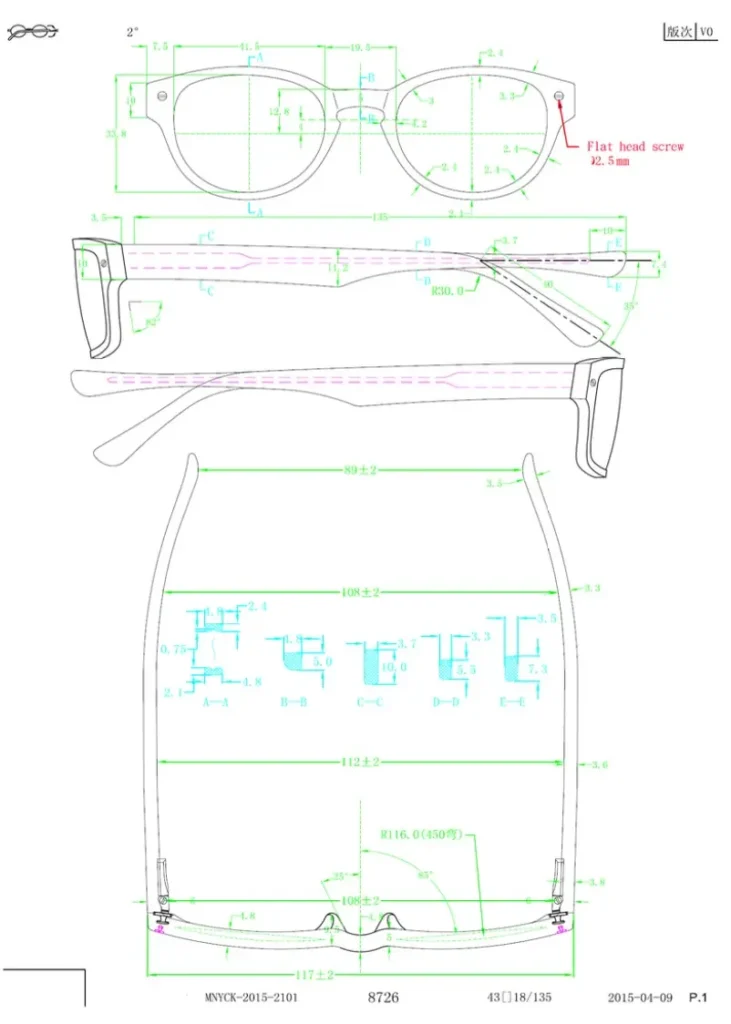
Sunglasses technical drawing is a representation of the samples being created or the final product. A technical drawing is important because this is what the sunglasses manufacturers will follow when sunglasses production. If the drawing is incorrect, the sample will be incorrect. Getting approval for a CAD will ensure that your sample will be very close to what Clients is looking for.
All Glasses technical drawing, including component drawings, must be in pdf and DXF form, 1:1 scale. The drawing must be labeled with the prototype number or model name/number and sizes and include detailed cross sections of the eye rim and any logo decorations for our reference.
Technical Drawings are required to be sent to approval before proceeding with first glasses samples, revised eyewear samples, and tooling samples.
Glasses Technical Drawing Optical Glossary :
Every industry has its own professional language, so we must be very clear about the following optical vocabulary. Only when we have a common language can we work together better and better standardize our most important glasses technical drawing.
Parts Of Sunglasses–Definition of all parts names for the glasses structure.
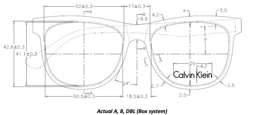
A Box Measurement-In frame or lens measurement, the longest horizontal distance from the furthest nasal point to the furthest temporal point of a shape, including the part of the lens in the groove. Referred to as the A size. This is the lens measurement, left to right.
B Box Measurement-In frame or lens measurement, the longest vertical distance from the topmost point to the bottom most point of a shape, including the part of the lens in the groove. Referred to as the B measurement. This is the lens measurement, top to bottom.
Base Curve-The front surface of the lens.
Bench Alignment (4-point touch) – Term used to describe the frame is properly adjusted when all four points touch the table. Both eye rims and both temple tips
Bevel-The ground inverted “shaped edge around the periphery of a lens necessary to hold the lens within the groove of a full rimmed frame.
DBL-(Distance Between Lenses)-The closest distance between lenses from the closest nasal point on one lens to the closest nasal point on the other lens. Also known as the bridge size.
Eye rim Curve-The measurement of the front curve of the eye rim only.
Figure 8- In semi rimless frames, the removable plastic that fits within the U-groove on the top eye rim.
Flex Hinges (Spring Hinges) –Spring loaded hinges that will return to original position after flexing.
Groove depth – Depth of the groove cavity measure from the rim edge to the bottom of the groove.
Hinge to hinge –The distance between the center hinge screw to the center hinge screw.
Injected frame – Process of forcing melted polymer into a mold cavity and cooling to achieve the desired product.
Nose pad/ Nasal Flange – On a plastic frame, the material near the bridge that protrudes and fits on either side of the nose to stop the frame from moving side to side.
Overall Front measurement – In frame fitting, the measurement from front view from end-piece to end- piece.
Pantoscopic Angle – In frame fitting it refers to the vertical angle which moves the bottom rim of the frame closer to the cheek.
Plug Size/ Window Size – The A or B measurement from rim edge to opposite rim edge. Not including the groove depth.
Regular hinges – Neither flex, nor stop hinge. Only opens and closes the temple.
Shield (Mask) – Consists of one large lens from left to right side that is shaped with an opening for the nose.
Stop Hinge – Used to stop a temple tip end from touching the back of the lens when temples are closed.
T-Profile – In milled semi-rimless frames, the top eye rim uses a T-profile created from the mold instead of a plastic bushing.
Temple Butt/ Temple Head – The end area of the temple where it is hinged to either the end-piece or the frame front.
Temple length – The distance from the center of the hinge screw to the temple tip end when the temple tip is extended straight.
The technical drawing MUST include the following information:
- Proto number or Model name/ number
- Sizes including A, B, DBL, and temple length
- Pantoscopic angle
- Temple tip bending angle and distance
- Base curve
- Head curve
- Nosepad/ flange height, angle and depth
- Overall front, Hinge to hinge, Temple Widest Point*, bend to bend*, and Tip to Tip measurements
- Groove shape and depth
- Cross sections of all decorations and logo treatments
We must also indicate a reference point of where it is being measured, for example the distance from the tip end (for the bend to bend measurement) and distance from the hinge break (for the widest point)
Note: The widest point measurement must be within 40-50 mm from the hinge break.
To avoid confusion or misinterpretation, when reviewing CAD drawings, follow the Best Practices below :
All line art (outline of all front shapes, temples, tips and parts that can be seen from the front view or top view of the frame) (Black)
Nose pads from front view and top view (Blue)
All dimensions (Green)
All center markings shown as a dashed line (Green)
All cross section labels, material labels, dimension labels etc. (Light Blue)
All Cad labels including revisions (Red)
All areas that cannot be seen from the outside of the frame that are typically shown with a dashed line (ex: screws, temple
tip core, hinges, rim-locks, back soldered eye-rims, etc.) (Pink).
Note: The colors requested are preferred but if a different color than what is listed is necessary this will not be an issue. All bullet points listed must be represented by a unique color.
*Do not use yellow on CAD drawings as it does not show up well when printed.
SUNGLASSES SIZING :
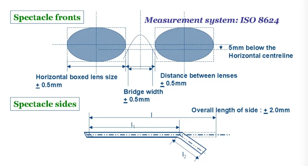
For optical and sun, sizes are based on the boxing method found in the International Standard ISO 8624 and will be approved during the tooling sample review. We must to follow the boxing system of measurement for both drawings and production.
It is important to note the box size is the true size of the lens. When looking at the lens in the frame, the horizontal size of the lens or “window” size of the lens plus the groove depth on the left side plus the groove depth on the right side makes the box size.
The DBL is the true distance between lenses which is the measurement of the bridge minus the groove depth of the left and right sides. The box symbol □ is required between the A size and the DBL size when stamped on the frame.
Per the ISO 8624, the temple length of the frame will be measured from the center hinge screw to the temple tip end when the temple is extended.
The box size A and DBL as well as the temple length will be marked on the frame.
Please note that the tolerances of the dimensions must be strictly controlled.

Electronic Frame Tracer

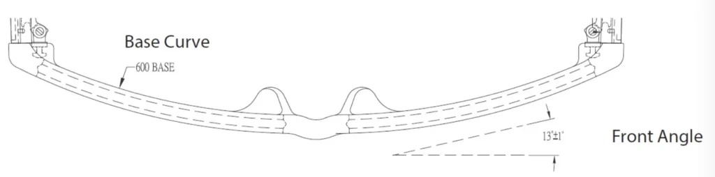
SUNGLASSES BASE CURVE/ FRONT ANGLE :
The amount of wrap the frame has is referred to as the base curve or front angle.
Our optical frame base curves can vary from 4 base to 6 base. Our sunglass base curves can be anywhere from 2 base and typically up to an 8 base though it can be more. The base curve of the demo or sun lens should match with the base curve of the eye rim to avoid lens cracking, lens popping out, or stress.
The front angle is the amount in degrees in which the frame front is bent, where the center of the bridge from top view is ninety degrees.
For Goggles
Base curve of goggles is determined by the lens curvature. It is expected that the lens and front curve match to minimize gaps and maximize lens security/ retention.
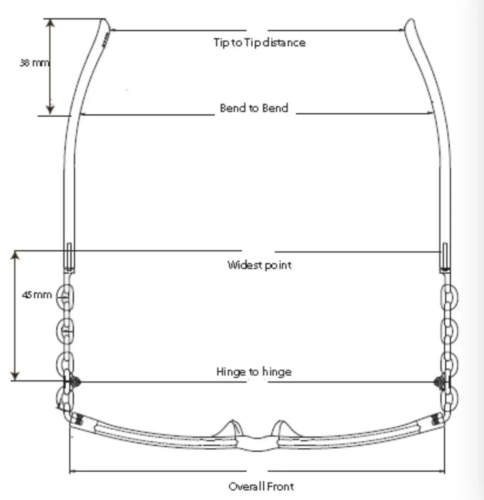
SUNGLASSES TEMPLE SPREAD MEASUREMENTS
The temple spread on each frame is measured at 5 different points to ensure a comfortable fit for our customer.
1. The overall front is the measurement from outside end-piece to outside end-piece.
2. The hinge to hinge distance or frame strap is measured from the center of the hinge screw on the right temple to the center of the hinge screw on the left temple.
3. The widest point is the widest measurement between the inside of both temples. This will ensure a smooth consistent inward curve. The factory must give a reference point measurement between 40-50 mm from the hinge cut.
4. The bend to bend measurement is on the inside of the temples at the mastoid bend (approximately 38 mm from the temple tip end).
5. The final measurement is between the temple tips.
SUNGLASSES PANTOSCOPIC ANGLE :
The pantoscopic angle is the vertical angle which moves the bottom rim of the frame closer to the cheek.
Typically, we require a pantoscopic angle for our optical frames to be between 7 and 12 degrees unless otherwise specified. Final pantoscopic angle will be determined during the tooling sample review.

To measure pantoscopic angle on a standard temple use the panto chart and measure from the center of the end- piece/ temple joint to the bottom of the ear bend. For non-standard temples measure toward the top edge of the temple to the bottom of the ear bend.

EYE RIM GROOVES :
There are multiple eye rim groove shapes and depths used in eyewear, however for maximum lens retention, the following must be observed:
